Sim Racing Hub
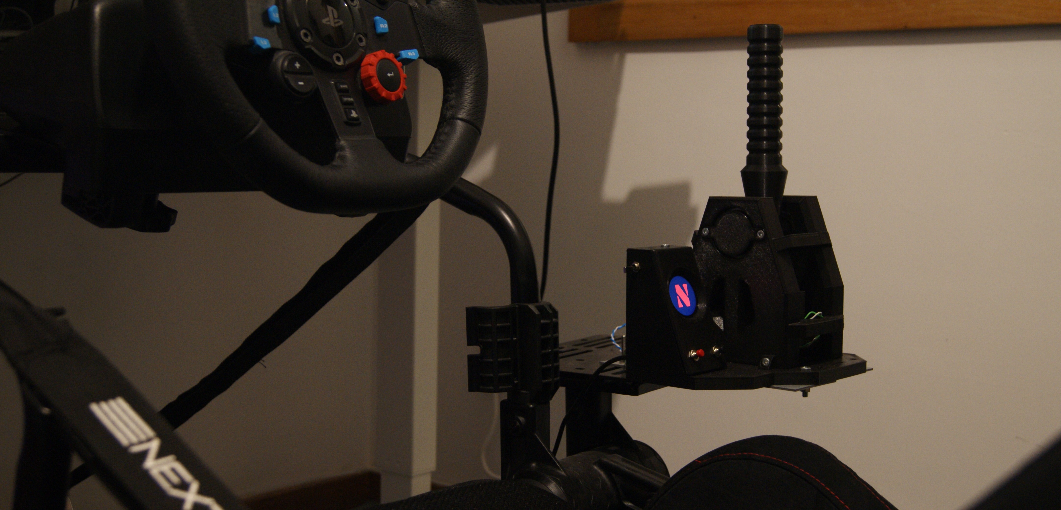
Table of contents Link to heading
Introduction Link to heading
The Sim Racing Hub is a new version of my old Racing Shifter, with some upgrades that I wanted to have in my old setup. I really liked the old shift functionality, but to quote Scott Adams
Normal people… believe that if it ain’t broke, don’t fix it. Engineers believe that if it ain’t broke, it doesn’t have enough features yet
New Features Link to heading
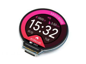
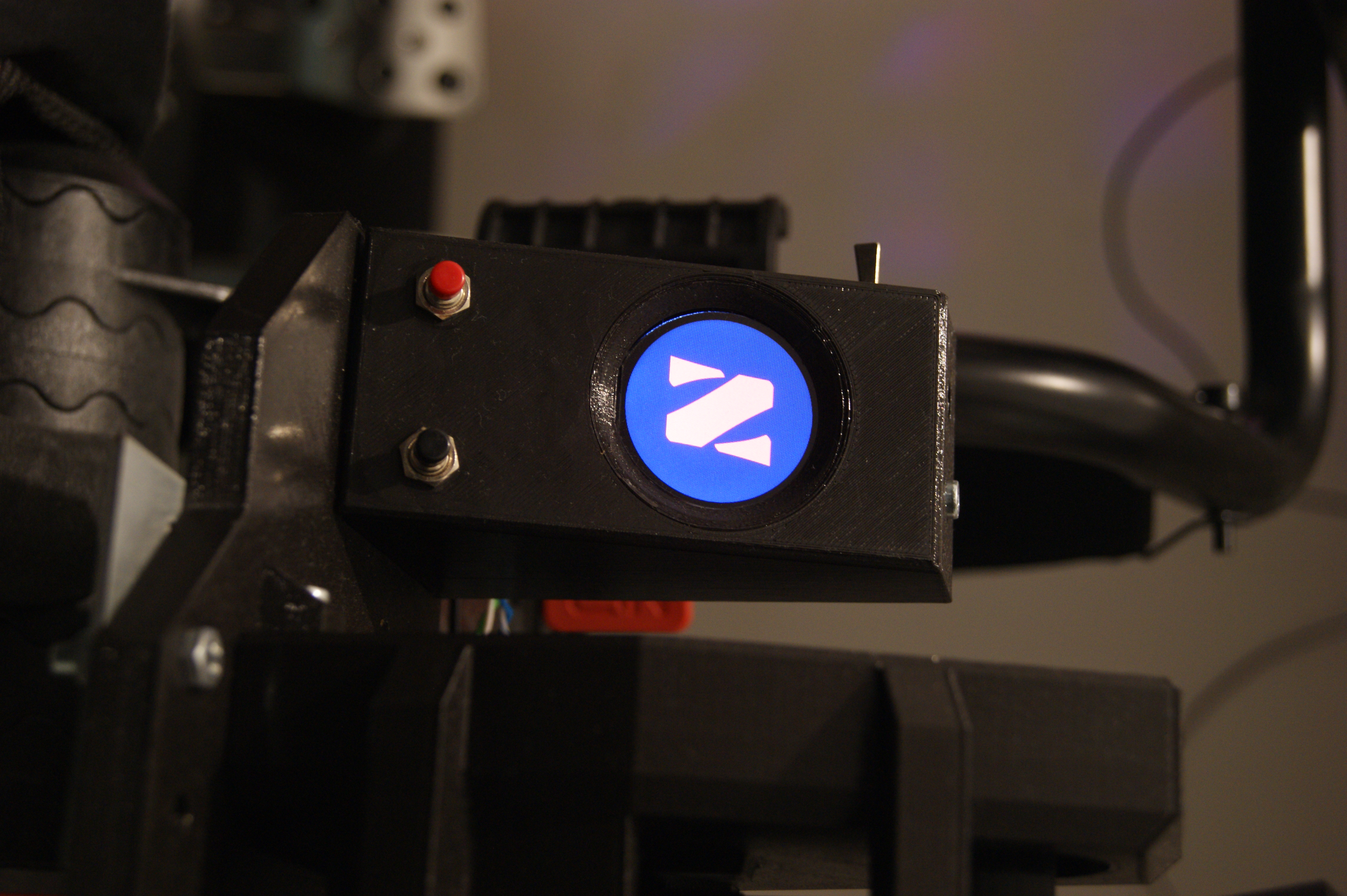
Better screen display Link to heading
The old gear display was a single digit 8 bit display, I want to enhance this a little bit to make it look better, so I had to search for a new solution.
The current gear should be the same as in game Link to heading
In the previous version, the displayed gear is calculated internally by the shifter, sometimes the communication between the shifter and the PC misses, meaning that from time to time its possible that the in game gear and the displayed gear are incorrect. Since telemetry is available in game, should be easy to transmit this to the shifter… right? right?!
Additional Inputs Link to heading
Besides the shifter functionality, I also want to have room for future developments, one of them is a analog handbrake. But I also want to future proof the design, so I added more digital inputs for further implementations.
Hardware procurement and development Link to heading
With this new requirements, I started searching for new hardware solutions. The best suited solution that I found was the waveshare RP2040. Its a RP2040 integrated with a round LCD display and GPIO headers.
The board schematic provided by waveshare shows that some of the GPIO pins are used for screen functions, so if we want to use the screen those IOs are already used up. Besides the screen, we need the following IOs:
| Type | Pin ID | Usage |
|---|---|---|
| DIO | 0 | Shift Up |
| DIO | 1 | Shift Down |
| DIO | 18 | Reserved |
| DIO | 19 | Reserved |
| DIO | 20 | Reserved |
| DIO | 21 | Reserved |
| ADC | 26 | ADCReserved2 |
| ADC | 27 | ADCReserved1 |
| ADC | 28 | ADCHandbrake |
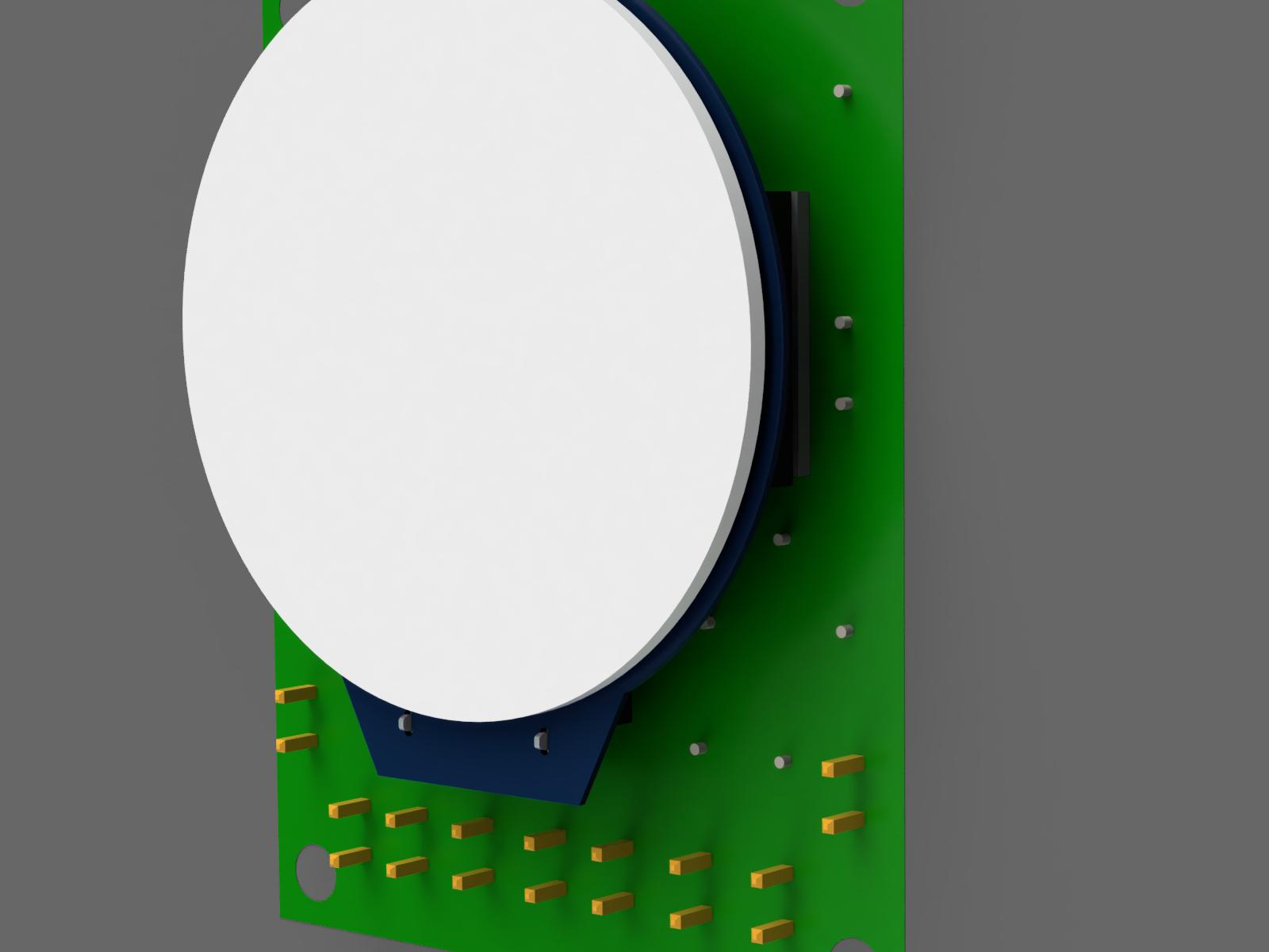
Having defined the IOs, I created a circuit board to handle the inputs. Of course you could just have a switch connected directly to the microcontroller input, however hardware buttons have a tendency to “bounce” quite a bit when activated. To reduce the chances of this bouncing creating multiple edge readings, I implemented a low pass filter on all digital inputs, this is always a good practice for any input really, this way you cut all high frequency interferences that might find their way to the micro input. For the ADC signals I created just a voltage divider, this is for when I get around to create the handbrake.
As digital inputs, I sourced the following:
- 2 x Microswitches
- 1 x Switch
- 1 x Black pressure button
- 1 x Red pressure button
The microswitches are for the shifter, the other inputs are for further developments.
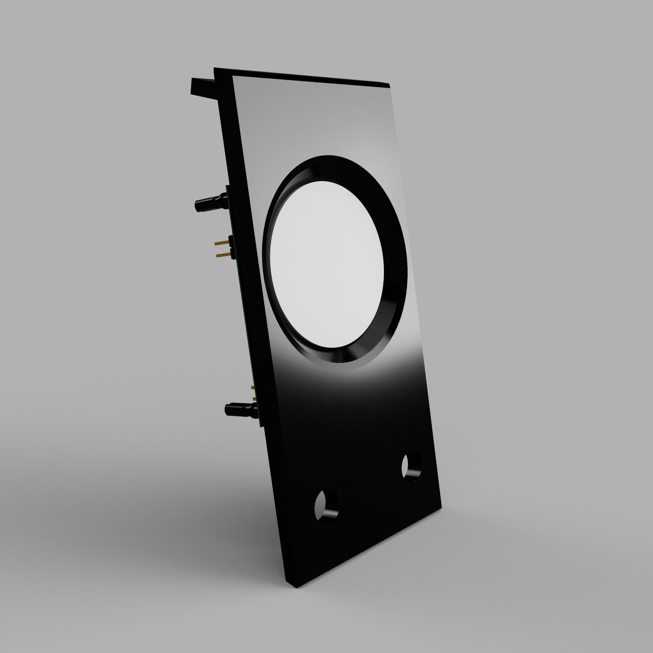
With this the procurement done, I created the circuit board. PCB back PCB front with waveshare RP2040 board connected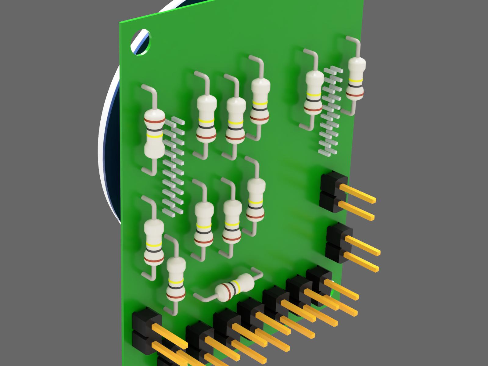
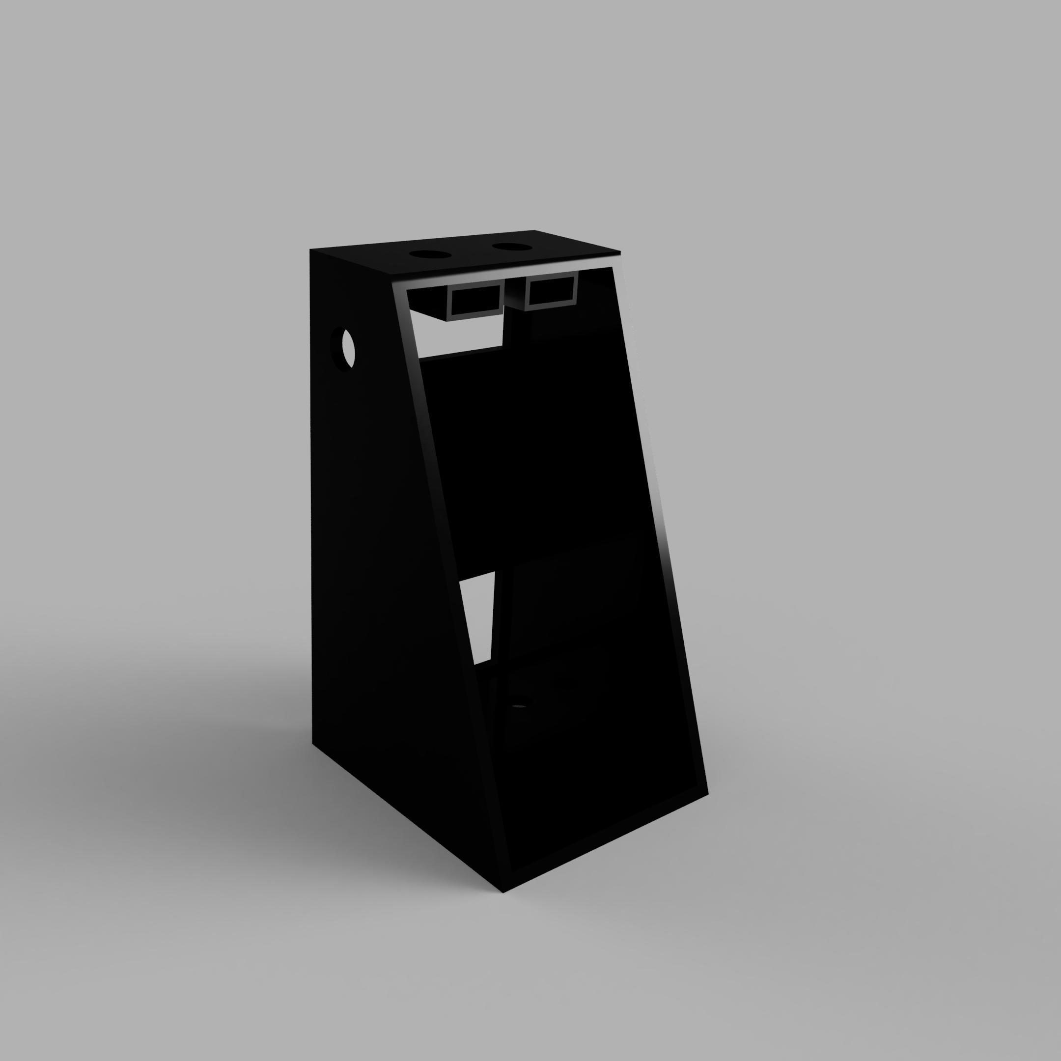
Housing Link to heading
As mentioned previously, this is a new version of an older project, so if you want more details on the entire build, please go to the instructables
For this version I just altered the base and the housing for the electronics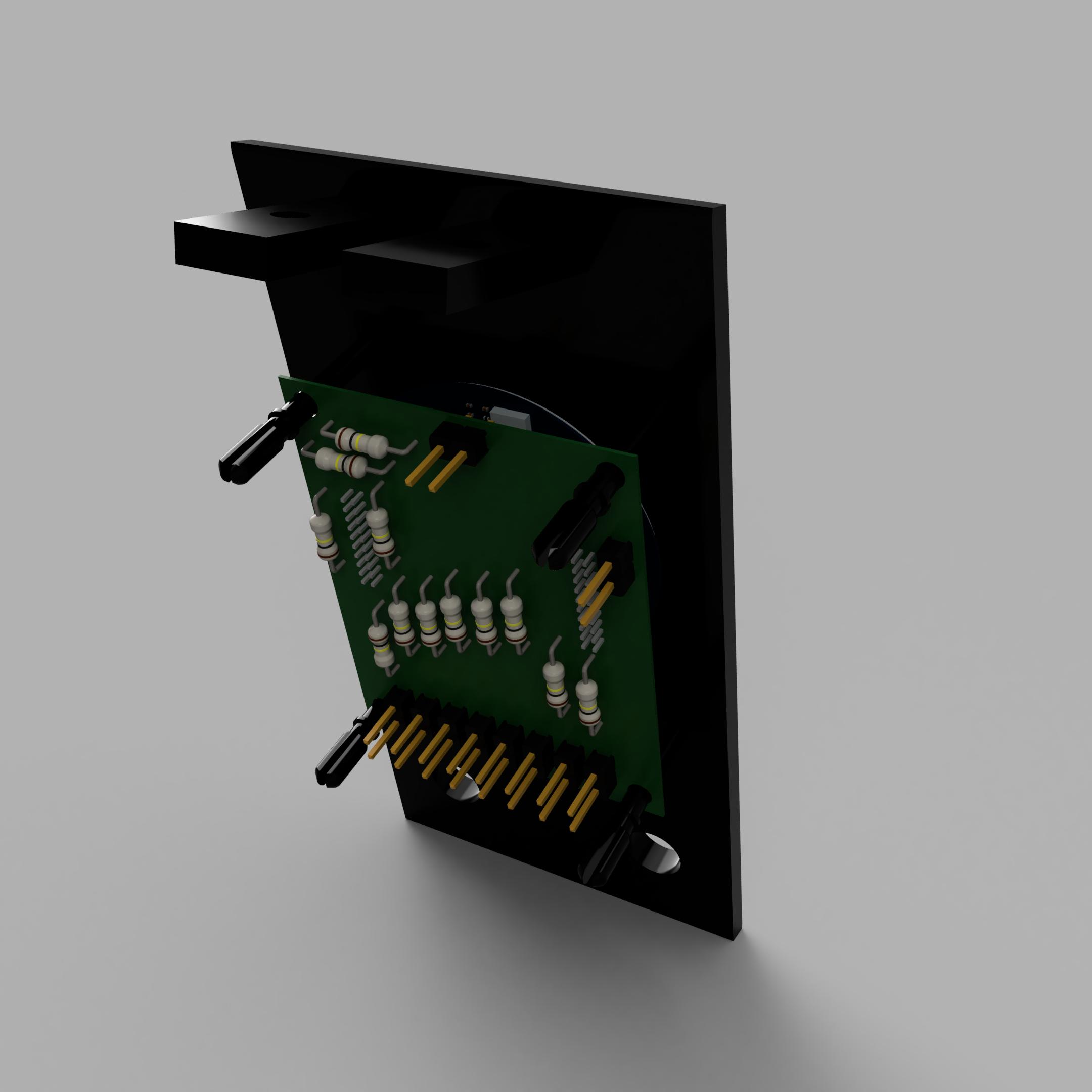
Software Link to heading
This is a distributed system, some of the software runs in the PC running the game and the remaining runs in the raspberry pi. In this post I will cover only the embedded software within the RP2040, I already went through the PC in this post. The microcontroller has two functions:
- Send shift request to PC
- Show current gear in the screen
I developed the project using platformIO beacuse I enjoy the flexibility of it. In the next sections I will go through a summary of the architecture, the HID communication and gear display.
Architecture Link to heading
The software project is structured in the following way:
- IO_inputs: Here all input handling is handled
- LCD: LCD display driver specific to the screen used
- ShifterLogic: Handles everything related with gear shifting
- UI: I used SquareLine Studio to generate the UI, more on that in a following section
- UIHandler: handling init and communication with the UI
- USBComm: Handling the HID communication
The RP2040 is a multicore microcontroller, so we need to split the tasks between both cores, and also its required to share information between both cores. The simplest way to share the information is using global variables, since in this application theres only one producer for each of the shared variables the chances to run into deadlocks is very limited. Therefore, the Information shared between all tasks is defined within the SharedDatatype structure:
1typedef volatile struct SharedDatatype
2{
3    uint8_t ShiftUpRequest;
4    uint8_t ShiftDownRequest;
5    uint8_t CurrentGear;
6}SharedData_t;
As you can see its not much, so the risk of deadlocks is not very high
On Core 0 runs the two tasks
IOinput.FastCyclic(&SharedData)- responsible for handling the inputs and turning it into shift requestUSBCommCyclic(&SharedData)- Handles the HID communication Core 1 runs the remaining twoUIHandlerCyclic(&SharedData)- responsible for the user interface screenShiftingLogic.step(&SharedData)- Handles all logic behind keeping current gear and handling shift up and shift down requests
HID Communication Link to heading
All HID communications are handled inside the USBComm module.
In order to allow two way communication and also gamepad behavior, I had to make the RP20040 behave as two HID reports. This was achieved by defining two
Adafruit_USBD_HID objects, one is a gamepad and the other is generic in and out.
Having two objects means that theres a chance different OSs and different games do not know how to handle this specific case. In windows 11 for example, the joystick game controller cannot display properly the inputs. In EASportsWRC, The first try to map always fail, but once you do a second mapping the game recognizes the correct HID report.
The generic inout HID is callback based for receiving communications. This is configurable through the .setReportCallback method from Adafruit USB HID:
 1void USBCommSet_report_callback(uint8_t report_id, hid_report_type_t report_type, uint8_t const* buffer, uint16_t bufsize)
 2{
 3  // This example doesn't use multiple report and report ID
 4  (void) report_id;
 5  (void) report_type;
 6  //Serial.print("Called Set Report Callback: ");
 7  //Serial.println(report_id);
 8  if(bufsize <= MAX_PACKET_SIZE)
 9  {
10    memcpy(ReceivedPacket,buffer,MAX_PACKET_SIZE);
11  }
12  // echo back anything we received from host
13  usb_hid_inout.sendReport(0, buffer, bufsize);
14}
buffer is the raw packet received via HID while ReceivedPacket is a shared buffer between the cyclic Comms task and this callback.
Theres more code than this, but its just for initialization and overall setup, if you want to see it in detail, take a look at Github
Display Link to heading
Finally, we get to the user interface development For the UI development, I used some available interfaces already created by waveshare to interact with the GV9A01 using the LovyanGFX For a faster UI development, I wanted to use a GUI designer instead of developing software only. After a quick search, I found out that using LVGL would allow me to use Squareline Studio for development of the UI.

The UI is rather simple, It shows only the gear currently selected. Everything related with handling the LVGL and UI is generated, on the UIHandler component we just have to handle the API calls.
The UIHanlerInit is called at startup and initializes the LovyanGFX, the LVGL and also the user interface, as shown below.
 1void UIHandlerInit(void)
 2{
 3    gfx.begin(PIN_LCD_SCLK, PIN_LCD_MOSI, PIN_LCD_DC, PIN_LCD_CS,
 4              PIN_LCD_RST, PIN_LCD_BL);
 5    lv_init();
 6    lv_disp_draw_buf_init( &draw_buf, buf[0], buf[1], screenWidth * 10 );
 7    /*Initialize the display*/
 8    static lv_disp_drv_t disp_drv;
 9    lv_disp_drv_init( &disp_drv );
10    /*Change the following line to your display resolution*/
11    disp_drv.hor_res = screenWidth;
12    disp_drv.ver_res = screenHeight;
13    disp_drv.flush_cb = my_disp_flush;
14    disp_drv.draw_buf = &draw_buf;
15    lv_disp_drv_register( &disp_drv );
16    /*Initialize the input device driver*/
17    static lv_indev_drv_t indev_drv;
18    lv_indev_drv_init( &indev_drv );
19    indev_drv.type = LV_INDEV_TYPE_POINTER;
20    indev_drv.read_cb = my_touchpad_read;
21    lv_indev_drv_register( &indev_drv );
22    ui_init();
23}
After initialization, UIHandlerCyclic is ran cyclically. Inside theres a small logic to transform raw gear data to ASCII characters and a call to the cyclic LVGL function that handles everything UI related.
 1void UIHandlerCyclic(SharedData_t *SharedData)
 2{
 3    uint8_t gear = SharedData->CurrentGear;
 4    //Serial.print("The curent gear is: ");
 5    //Serial.println(SharedData->CurrentGear);
 6    if(10 == gear)
 7    {
 8        _ui_label_set_property(uic_CurrentGear,_UI_LABEL_PROPERTY_TEXT,"R");
 9    }
10    else if(0 == gear)
11    {
12        _ui_label_set_property(uic_CurrentGear,_UI_LABEL_PROPERTY_TEXT,"N");
13    }
14    else
15    {
16        _ui_label_set_property(uic_CurrentGear,_UI_LABEL_PROPERTY_TEXT,String(gear).c_str());
17    }
18    lv_timer_handler(); /* let the GUI do its work */
19
20}
Final Build Link to heading
I screwed up on the first set PCBs, so I ended sending to jobs to be fabricated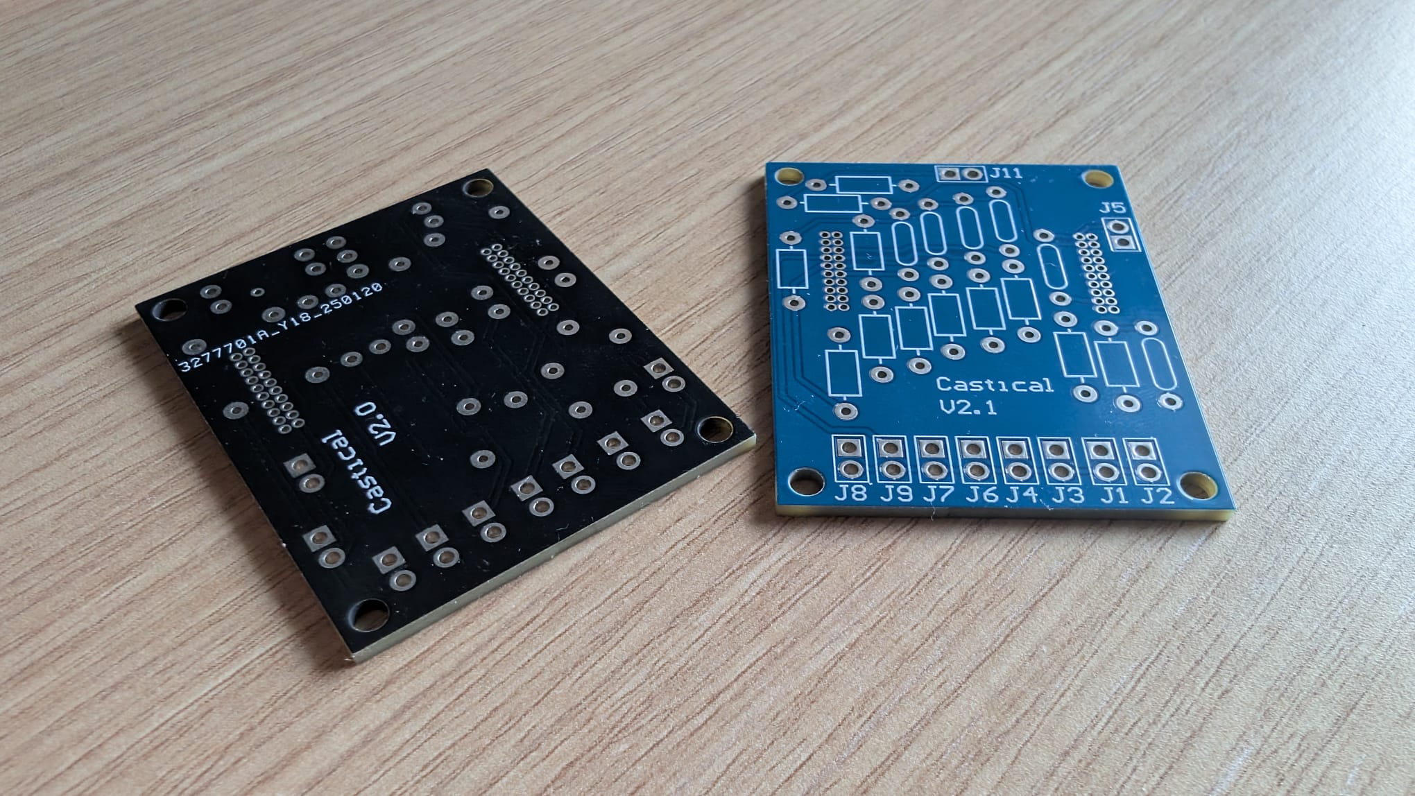
The final build looks like this:
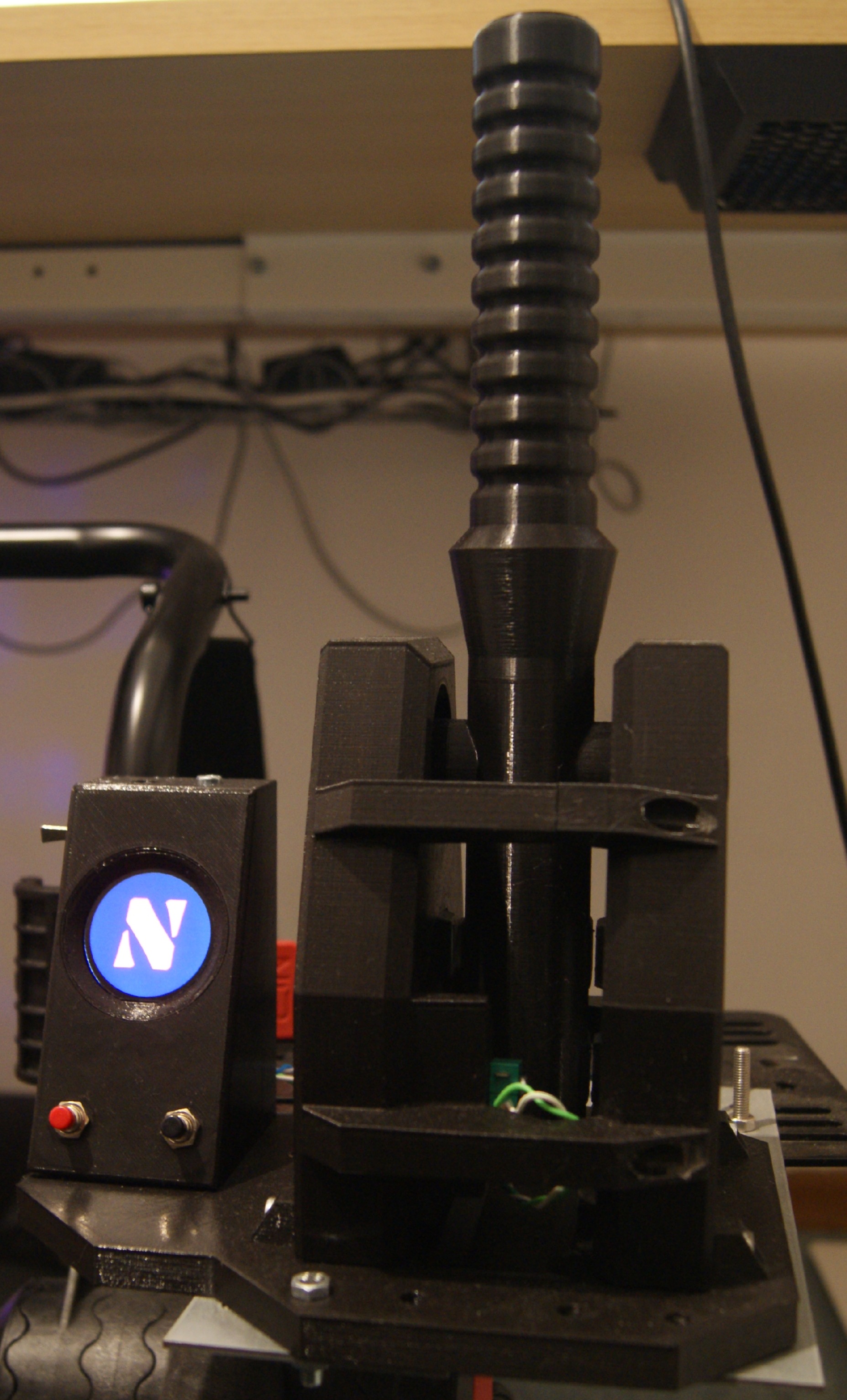
As you can see, it looks very similar to the old Sim racing shifter (almost seems this a second version of the old one 😄) The biggest difference is the display and control board:
Conclusion Link to heading
Hope you enjoyed reading through this small upgrade to my shifter. Any questions you might have feel free to reach out to me, Im available for questions and comments. I will upload briefly the 3D printer parts to Printables and also maybe update the instructable (not sure yet if I wont just create a new post there). All software is already available in Github 😄
If you like my projects please consider supporting my hobby by buying me a coffee☕ 😄