The Next Generation - ESP32-S3 Touchscreen Inclinometer Link to heading
While I built my earlier Car Inclinometer project with the RP2040, I ran into a couple of setbacks. The previous version was great, but I wanted something more stable and capable. If you look at that repo, you will find that I actually updated the project to use a RP2350.
Even with this update I was ending in some weird states which were making developing the software quite challenging. I was having random deadlock situations caused by the i2c bus that I was unable to debug, since the board I was using did not provide a way to connect the Raspberry Pi debug probe.
It was one of those “It can be running for three days without an issue, but if I look at it funny, it will break”. That can be demoralizing. My last ditch attempt with that board was implementing a watchdog callback. But thats not a permanent solution, so I kinda demoralized and left the project die out.
However, I still wanted to create this inclinometer, so I started the search for a substitute board. I found once again a solution via Waveshare, the Waveshare ESP32-S3 Touch AMOLED.
The Vision Link to heading
My goal was to enhance my previous approach with an embedded touchscreen system that could:
- Display real-time inclinometer data (roll and pitch)
- Provide a responsive, modern user interface
- Support future expansion with additional sensors and screens
- Be completely over-the-air updateable
- Act as a small hub for vehicle telemetry and other things I might implement 👀
- Be able to debug it
- Use C++ features to create a cleaner architecture
The result is a system built on LVGL, and ESP-IDF that makes it easy to develop custom gauges and displays for any embedded or automotive application.
Hardware Selection Link to heading
For this project, As previously mentioned, I chose the Waveshare ESP32-S3 Touch AMOLED board as the foundation. The ESP32-S3 is a powerhouse compared to the RP2040/RP2350 - dual-core processor, more RAM, more flash, and native WiFi/BLE support.
The board includes:
- 1.75" AMOLED display (454x454 pixels)
- Touch controller (GT911)
- IMU (QMI8658) - the heart of our inclinometer
- Expansion headers for additional sensors
I designed the code to be flexible enough to support multiple sensor variants, so you can adapt it to different hardware configurations.
Building the User Interface Link to heading
Touchscreen dashboard designed in SquareLine Studio
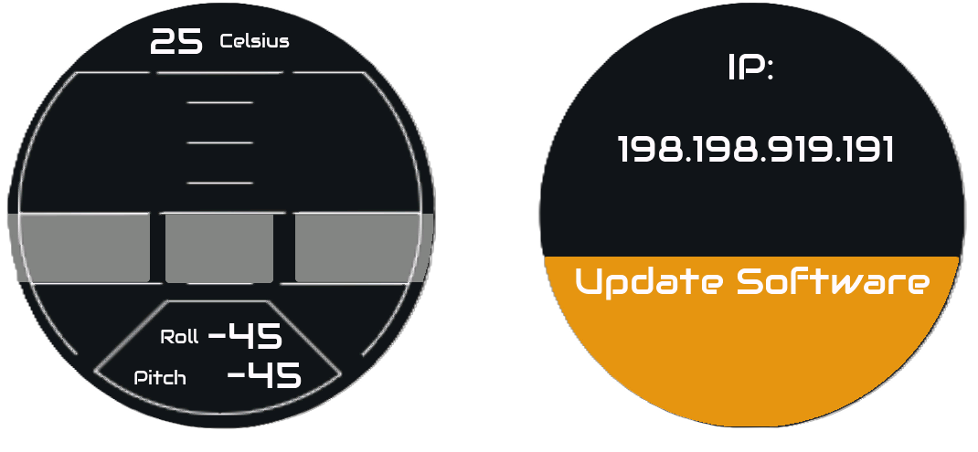
The resulting interface features:
- Main inclinometer display with live roll and pitch data
- Arc gauges showing vehicle tilt angles (-45° to +45°)
- Central pitch indicator as a vertical slider
- Real-time numeric readouts showing actual roll and pitch values and temperature
- Multi-page support for future expansions (vehicle telemetry, settings, diagnostics)
- Software Update Button to allow for over the air updates
The beauty of this approach is that:
- All UI changes happen in SquareLine Studio (no manual C code editing)
- The exported code integrates seamlessly into the firmware
- Application logic remains completely decoupled from the UI layer
- Screens can be redesigned without touching the sensor reading logic
Implementation Architecture Link to heading
Sensor Data Processing Link to heading
Just like in the previous project, the inclinometer relies on processing accelerometer data from the IMU. Previously, the calculation was simply done by calculating the angle of the gravity vector relative to the board’s axes, with these two simple transformations:
$$roll = \arctan\left(\frac{y}{-x}\right)$$
$$pitch = \arctan\left(\frac{z}{-x}\right)$$
In the new ESP board, the accelerometer is mounted in a different orientation within the board, making the roll and pitch calculation different:
$$roll = \arctan\left(\frac{y}{\sqrt{x^2 + z^2}}\right)$$
$$pitch = \arctan\left(\frac{z}{x}\right)$$
These values are then scaled to fit the display gauges and text labels in real-time.
How data is sent to the UI Link to heading
To transfer the measured roll and pitch, I rely on the FreeRTOS built in xQueue method.
At startup, both the qmi8652cInterface and Display object take a queue reference owned by the system.
The queue is filled i
This queue contains this structure:
1struct RollPitch
2{
3    float roll = 0.0f;
4    float pitch = 0.0f;
5    float temperature = 0.0f;
6};
Project Structure Link to heading
The firmware is organized into clean, modular components:
CarTouchScreenMiniDisplay_ESP32S3/
├── main/                    # Application entry point
│   ├── tasks initialization
│   ├── sensor polling loops
│   └── main firmware logic
│
├── components/
│   ├── display/            # Display driver & LVGL integration
│   │   ├── touch input handling
│   │   └── rendering loop
│   │
│   ├── ui/                 # SquareLine Studio generated UI
│   │   ├── screens
│   │   ├── widgets
│   │   ├── fonts
│   │   └── images
│   │
│   ├── SensorLib/          # Modular sensor drivers
│   │   ├── QMI8658 IMU interface
│   │   ├── Optional: QMC6310 magnetometer
│   │   ├── Optional: LTR553 light sensor
│   │   └── Optional: DRV2605 haptic motor
│   │
│   ├── System/             # FreeRTOS task coordination
│   │   ├── sensor reading tasks
│   │   ├── display update tasks
│   │   └── system state management
│   │
│   ├── OTAUpdater/         # Over-the-air update handler
│   │   └── automatic version checking & flashing
│   │
│   └── esp_lcd_sh8601/     # LCD controller driver
│       └── hardware interface layer
│
├── SquarelineProject/      # SquareLine Studio project file
└── partitions.csv          # Flash layout for OTA updates
Key Design Decisions Link to heading
1. FreeRTOS Task Architecture
I used FreeRTOS tasks with queue-based communication to keep the system responsive. Sensor reading, UI updates, and display rendering run in parallel without blocking.
2. UI Separation
The application logic knows nothing about the UI. Screen updates happen through a clean abstraction layer. This means I can completely redesign the interface without touching the sensor code.
3. Component-Based Sensors
Each sensor is self-contained. Need to add a magnetometer? Drop in the new component.
Over-The-Air Updates Link to heading
One powerful feature I built in is OTA (Over-The-Air) update capability. Rather than physically connecting to the device with USB every time you want to update firmware, the ESP32-S3 can install new versions over WiFi.
This was crucial because I wanted the device to be permanently mounted in the vehicle. The OTA system uses the dual-partition scheme - one active partition and one for updates - ensuring you always have a bootable system even if an update fails.
How events are handled between UI and OTA Link to heading
So I already showed you how I shared data between the inclinometer sensor and the UI, but now we have a different challenge, instead of sharing data, we now need to trigger events. I wanted to do this using the least amount of overhead possible, that meant keeping the code in my top level system class as minimal as possible.
As you already saw in the UI image, I created a big ass orange button (to be fair, the screen is not that big). I want to trigger the update mechanism via this button.
So what I want to do:
Looking at the flowchart it looks simple, now to the actual implementation.
Both OTA Updater and Display are owned and initialized by a top level system class. Could I maybe implement a routine where the updater is called directly by display? Sure, but I had two reasons to build it this way.
- I want all constructors and initializations to be easily findable in the top class
- The OTA updater class right now does more than just software update (It also handles wifi connection)
Due to this, I’m left with a double dependency, Display shall be able to trigger a routine in OTA Updater which should trigger a member change back in the display.
After searching for a bit and playing with some solutions, I ended up with using std::function<> as a wrap for the callbacks, as this is exactly one of the uses cases where this template class should be used. It basically wraps a callable object in a class which allows us to pass functions as arguments to other functions, which is exactly what we want to do here.
1class Display{
2    std::function<void(lv_event_t* )> m_SoftwareUpdateHandler;
3    //Set at initialization by setSoftwareUpdateHandler
4    void setSoftwareUpdateHandler(std::function<void(lv_event_t* )> callback)
5    {
6        m_SoftwareUpdateHandler = std::move(callback);
7    }
8}
Now when I call this set function, I can pass as argument the method from my software updating class, the same was done the other way around.
1class OTAUpdater{
2    std::function<void(const std::string&)>  m_SWUpdateFeedbackCallback;
3    //Set at initialization by setSWUpdateFeedback
4    setSWUpdateFeedback(std::function<void(const std::string&)> callback)
5    {
6        m_SWUpdateFeedbackCallback = std::move(callback);
7    }
8}
Now at system startup, we set the callbacks for both classes:
 1class System{
 2        /**
 3         * Callback setting
 4         */
 5        display.setSoftwareUpdateHandler(
 6            [this](lv_event_t* e)
 7            {
 8                OTAUpd.triggerUpdate();
 9            });
10
11        OTAUpd.setSWUpdateFeedback(
12            [this](const std::string& msg)
13            {
14                display.SWUpdateFeedback(msg);
15            }
16        );
17}
Using these lambda functions here allow us to have loose coupling between the display and ota classes without having to create complex dependencies.
If you want to build this yourself: Link to heading
Prerequisites Link to heading
- ESP-IDF v5.0+ (follow the official setup guide)
- Waveshare ESP32-S3 Touch AMOLED board
- SquareLine Studio 1.6.0+ (optional, only if modifying the UI)
- CMake 3.16+
Build & Flash Link to heading
# Clone the repository
git clone https://github.com/CarlosAlmeida4/CarTouchScreenMiniDisplay_ESP32S3.git
cd CarTouchScreenMiniDisplay_ESP32S3

# Configure for ESP32-S3
idf.py set-target esp32s3
idf.py menuconfig  # Enable PSRAM, set clock to 240MHz

# Build and flash
idf.py build
idf.py -p COM3 flash monitor  # Windows (adjust COM port)
The device will boot up with the inclinometer screen running. Tilt your board and watch the gauges respond in real-time!
Customizing the UI Link to heading
To modify the dashboard design:
- Open
SquarelineProject/CarTouchScreenMiniDisplay.slvsin SquareLine Studio - Edit screens and components as needed
- Export to
components/ui/(select “ESP-IDF” target) - Rebuild:
idf.py build && idf.py flash
What’s Next? Link to heading
This framework is designed to be extended. Some ideas:
- Multi-screen system: Navigation between inclinometer, telemetry, diagnostics
- Sensor fusion: Combine IMU data with magnetometer for heading information
- Data logging: Record vehicle data to SD card or cloud
- Custom gauges: Build analog-style gauges, progress bars, real-time graphs
- Vehicle Integration: Connect to other vehicle sensors for engine parameters
The modular architecture makes all of this possible without major rewrites.
Conclusion Link to heading
This project represents a significant step forward from my initial RP2040/RP2350 inclinometer, but not the finished product yet, now we get to the fun part I like to call Integration Hell. Stay tuned for the next step where I develop the mounting brackets and hardware connections to the vehicle wiring loom.
If you found this project interesting or useful, please consider supporting my work:
The code is available on GitHub and released under MIT license - feel free to use, modify, and share!